APS112 Engineering Notebook
This is my engineering notebook for APS112, which I created using Obsidian MD. Therefore, it is originally a markdown file. If there are any issues with the .pdf version, please instead view the markdown version, which can be viewed on my website.
| Information table | |
|---|---|
| Name | Matthew Kong |
| Student Number | 1011013458 |
| Course | APS112 |
| Session | 2025W |
| Tutorial section | TUT0113 |
Lecture 4 Questions (Team Considerations)
Thursday, January 16th, 2025
- What are some strengths you brought to your ESP 1 team? What unique skills or experiences do you bring?
- Persistence
- Emphasis on quality control and revision
- Formatting and graphic design abilities (important for figures)
- Willing to work overtime to complete project if necessary
- What are some challenges that people may have working with you? Some questions to guide your thinking - Do you have a long commute? Do you have a lot of extra-curricular activities or hours for a part-time job? Do you have certain days of the week or times of the day when you can’t work?
- At times I am a perfectionist, so I have trouble letting go or compromising—even under a short deadline.
- My commute is short, but I'm not that willing to meet up in person after school hours.
- What do you want to get out of this project? Why are you in engineering and how will working on this project align with that and what you hope to achieve?
- I want a better grasp over how to deal with crises as a team, especially since my last ESP team struggled through many crises.
- I also want to understand how to better pace myself through projects, since I struggled with that a lot last semester; I would often find myself working until 3 in the morning, trying to complete a section of the PR or CDS.
- What worked well in your ESP 1 team? What worked poorly?
- ✅ Most of us were committed to success, albeit with varying definitions of the term.
- ✅ There wasn't much non-project related conflict.
- ❌ Time management was quite poor in the team as a whole.
- ❌ We did not deal with crises well at all; when we had to change a significant amount of our CDS, half of my team effectively disappeared.
- What do you want to ensure happens in your ESP 2 team as a result?
- Stick to internal deadline schedule as much as possible.
- Increase the amount of communication we have with CI/TA/EM, as well as earlier, to get feedback on our assignments if possible.
Team, CI, EM, & TA Contact Information
TUESDAY, January 21ST, 2025
Table 1 includes contact information for my entire team, and Table 2 includes contact information for my CI, TA, and EM.
Table 1. Contact information for my team.
Team Meeting Notes: Team Charter
Friday, january 24th, 2025
In our team meeting today, we discussed the incomplete sections of our TC. Specifically, the team roles were a bit murky, since we did not know what roles were required.
- By consulting the textbook, we selected a few that we believe would be important for us to include.
- In particular, we chose ones that: a) we believe we had strengths in, and b) thought would benefit our team cohesion.
I voluntarily chose the multimodality/formatting coordinator role because I believed I was most fit for it, given my experience in graphic design. Ruya and Sanaz both voluntarily chose the project manager and team leader roles respectively. For the other team members though, they just chose roles from the textbook that they thought would benefit the team. Table 1 has a full list of the team members and their roles.
Table 1. Names of team members and their roles/responsibilities
| Team Member | Role | Responsibilities |
|---|---|---|
| Ansh Shah | Communication Liaison | - Writing emails and sharing documents with client - Communicating with CI/TA/EM on behalf of team |
| Aryan Athavale | Meeting/Schedule Coordinator | - Scheduling team meetings (time/location) - Writing meeting agenda and minutes - Setting meeting reminders |
| Parth Talati | Quality Assurance Coordinator | - Proofreading documents, ensuring rubric standards under “Exceeds Expectations” are met - Conducting thorough edits and final checks |
| Sanaz Amirnezhad | Team Leader | - Managing team communication, resolving conflicts - Monitoring project progress ensuring deadlines are met - Communicating group concerns and feedback with instructors |
| Elif Ruya Balta | Project Manager | - Distributing tasks among members - Tracking team members’ progress |
| Matthew Kong | Multimodality/Formatting Coordinator | - Choosing effective mode types. - Creating graphics for project documents. - Establishing templates and formatting procedures. |
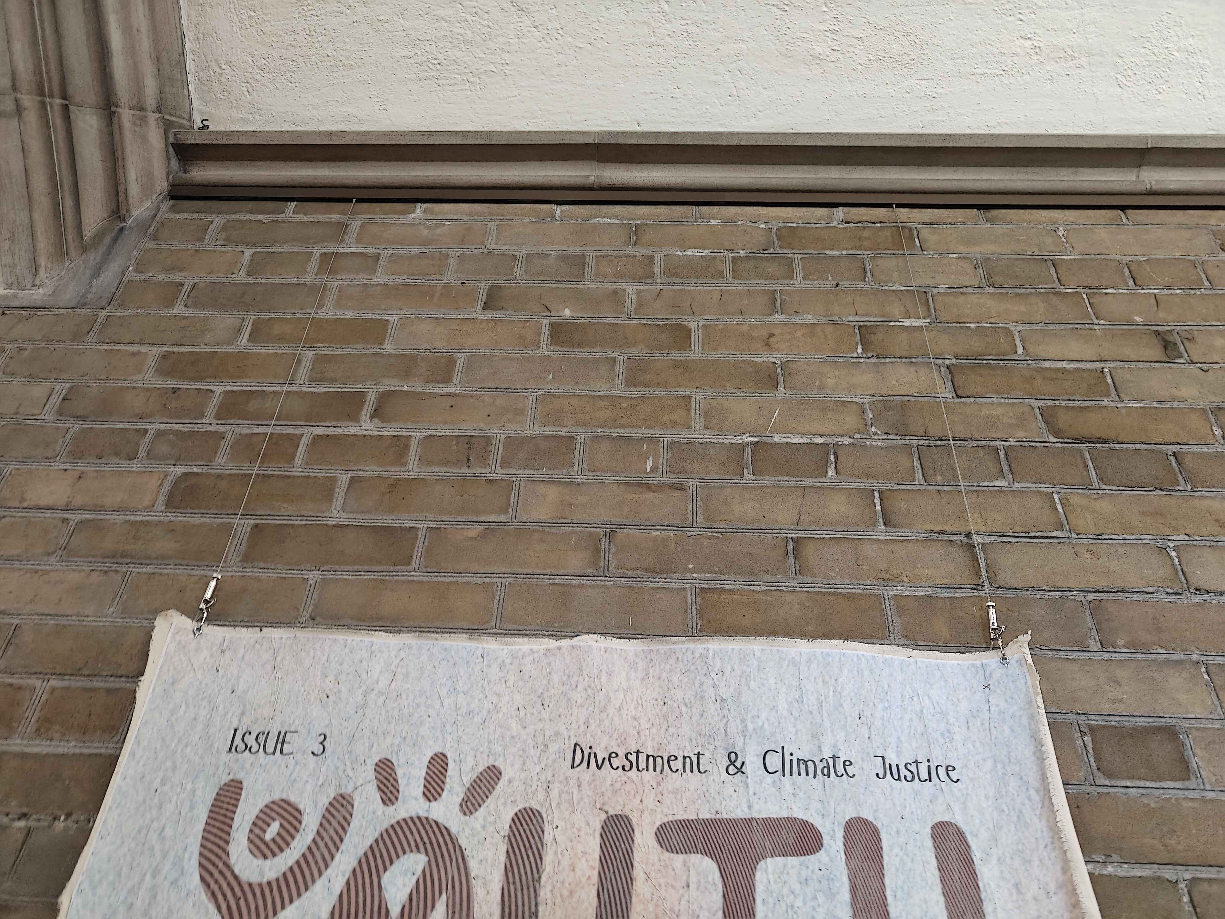
Client Meeting #1 Notes
Thursday, January 30th, 2025 (13:00 to 13:30)
A collection of jot nots taken during my team's meeting with our client.
- Client's name is Sasa Rajsic
- First name pronunciation:
/ˈsɑːʃə/ SAH-shə
- Integrated Arts Education Coordinator at Hart House
- First name pronunciation:
- The building is a historic building
- There are many physical restrictions
- Cannot change the walls at all, without proper reasoning
- Client also mentioned "you will inevitably have to drill a few holes in the wall, we would just like to keep the amount of holes low"
- Currently art is hung by pre-existing supports
- Environment is not very regulated.
- Hot and cold air drafts come in frequently
- Humidity fluctuates a lot
- This affects artwork that is made of organic materials
- Right now the client only displays prints, which aren't affected
- Client says protecting the artwork is not a priority, since he intends to keep them as prints.
- This affects artwork that is made of organic materials
- Users are often not very observant of surroundings.
- Public space; anybody can come in and accidentally bump artwork with backpacks
- The area is a "high traffic" space, lots of people using hallways for purposes other than observing artwork
- Client's needs (stated by client themselves)
- Looking for solution to allow them to show prints
- Modular aspect is very important
- Quickly, efficiently, and cheaply swap artworks
- Small team (two people?) in charge of swapping artworks
- Very text-heavy artwork
- Budget is not specified
- There is supposedly a donor, but the amount of funding they receive is unknown at this time.
- "[...] could be up to $100,000, think of it as if you have a lot of budget" - Sasa Rajsic
- Aesthetics of display unit are important to client
- "[...] design should be functional, good looking, clean" - Sasa Rajsic
- Can draw inspiration from Neo-Gothic architecture of Hart House, or create something more contemporary.
- "[...] don't worry about fitting Neo-Gothin style" - Sasa Rajsic
- Client wants 1 or 2 more check-ins before next meeting.
- Wants to "see what you've come up with"
- My interpretation is that he wants to see what solutions we've come up with?
- This is not quite the order of the engineering design process we were taught...
Team Meeting Notes: Problem Definition
Friday, January 31st, 2025
As we began to work on the PR, we needed to properly define the gap, need, and scope of our project. In our team meeting today, we discussed this thoroughly. Below is what we identified the gap, need, and scope to be.
- Gap: lack of a display system that adjusts to prints of varying sizes without requiring fully dismantling the system, while protecting prints from abrasion
- Need: a display system—including the selection of a viable material for prints—that protects prints from damage while accommodating prints of various sizes
- Scope:
- Use pre-existing materials for art prints instead of developing new materials
- Only defined in the main hallway, close to the front desk
- Only involves flat, printed artworks
- Since Hart House is a historic site, conservation efforts by UofT prevent most modifications to the building, including attaching frames directly to the walls
Initial Possible Solution: Tsugite Joints
Friday, January 31st, 2025
Our client wanted 1-2 more check-ins before the next formal client meeting, likely with the expectation that we would have come up with some solutions already. So, I thought of a solution. I haven't done the PR yet, so this is a very early, initial idea—nothing official yet.
This idea is for a display frame that would be built using small, interlocking modules, thus enabling it to be rebuilt to virtually any size. The interlocking mechanism could be similar to Tsugite joints, which I read about here in this paper.
PR: Service Environment
Thursday, February 6th, 2025
This was my section of the PR, and thus I am tasked with planning out what to include in it. Below are some notes I took in preparation.
- Humidity and temperature, while very important to our project, is not easily measurable since we can't measure during different seasons or times of the year.
- Perhaps we can use pre-existing values/measurements, for Toronto as a whole?
- The issue with the above method is that it's not necessarily representative of the environment inside of the Hart House
- However, client did mention that the hallways are subject to changes in outdoor temperature/humidity, since the doors open a lot and it's a public space
- We can try to justify our values by comparing humidity and temperature values in similar buildings? If I can find something on that
- For next engineering observation, observe:
- Do light measurements for hallways on second floor and basement.
- Note down where fire hydrants are
- Measure width of hallways and height of walls
Team Meeting Notes: FOCs
Friday, February 7th, 2025
In our team meeting, we discussed the FOCs. The functions in particular were a point of contention, since my team had difficulty with specific wording.
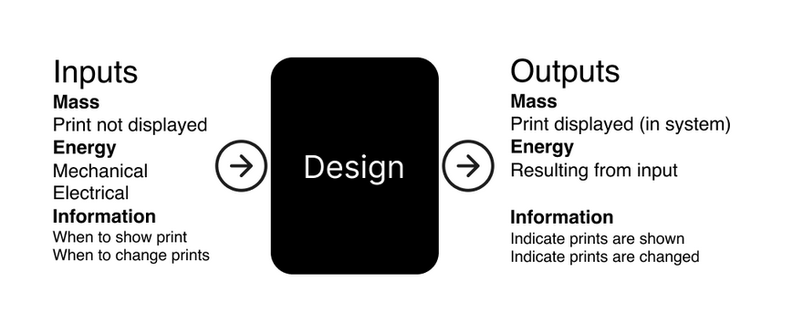
Functions: Black Box Method
My team initially had difficult coming up with meaningful functions outside of just "display prints". So, we employed the black box method.
Objectives/Constraints: Notable Issues
I wasn't in charge of these sections personally, as a few other team members were tasked with it. However, they raised issues in regards to finding specific metrics. For example, finding specific metrics for:
- Affordability (we didn't know a budget at the time)
- Ease of assembly (we didn't know what specific metrics constituted this)
- Print size accommodation (we didn't know how to define this metric)
- Preservation of the historical nature of Hart House (we didn't know what specifically we needed to do with this constraint to fulfill it)
As of writing, my team is still unsure of how to address these issues with the metrics.
Tutorial: PR Debrief Notes
Tuesday, February 25th, 2025
In tutorial, our TA gave us feedback verbally on what parts of the PR to improve on. Below are my rough notes.
- Exec summary:
- Doesn't mention the cost of prints, despite being in other parts of the document
- Unnecessary bolding of "prints" word
- Problem statement:
- Overly long and unconcise; need statement is somewhat difficult to read
- Service environment:
- Very thorough
- Effective charts - TA was very impressed by light-level heatmap
- Stakeholders:
- Student groups and artists should be split
- Impact description doesn't fit both groups
- Student groups and artists should be split
- Functions:
- Introductions should be a lot more specific (doesn't have to mention specific FOCs, but mentioning the project specifically helps)
- Functions well thought out
- Objectives:
- Costs objective should be much more specific; should describe how costs are derived, instead of blanket "$4000 yearly"
- Be more consistent with text formatting; use only simplified less than or equals sign
- Constraints:
- Number of sections is too nonspecific as a metric for the Fire Code constraint
- Conclusion:
- Functions not mentioned?
CDS: Idea Generation Part 1
Friday, February 28th, 2025
For the CDS, we had to come up with 50+ solutions. To do this, during our team meeting, our team decided that each team member should come up with 5 unique means for each secondary function in a morph chart, and from there, we would generate our solutions. Table 1 shows the means I generated.
Table 1. Morph chart of solutions I generated
| Protect prints from physical damage. | Preserve visibility of prints. | Facilitate the switching of art prints when required. | Adjust to varying sizes of prints |
|---|---|---|---|
| Rollable protective tube that covers artwork at the back, spray adhesive at the front | Motion-activated lighting | Spring loaded clamps (simply squeeze and release to swap) | Layered paper/mats that fill in space when displaying smaller prints within a larger frame |
| Grid pattern cage in front of artwork made of thin metal wires, spaced 5 cm apart | Mirror system to reflect artwork to different angles | Prints attached to thin metallic frame; frame attached to display unit via suction cups | Frame made of small (20 x 5 x 5 cm) wood modules that interlock using Tsugite joints, locked in place using metal rods; supported by metal truss backbone |
| Large signs above frames saying "DO NOT TOUCH" | Frame that has digital monitors on its sides, which display a camera feed of the inside of the frame (i.e., the artwork) | tape :/ | Frame made of small (20 x 5 x 5 cm) wood modules that interlock using Neodymium magnets; supported by metal truss backbone that is held in place by magnets |
| Ultrasonic sensor attached to top of frame, detecting viewers' proximity to frame; if viewer gets too close to frame, a speaker makes a loud "BEEP" sound | Display unit mounted to motorized arm and ultrasonic sensor that tracks positioning of viewer, and tilts artwork to orient towards viewer | All four corners of print have holes, which attach to a backbone using metallic hooks; quick-release mechanism | Polymer frame that expands or shrinks with heat, and when rapidly cooled, retains the new size |
| Note that one row was removed due to being filtered out in a feasibility check. |
CDS: Idea Generation Part 2 + Idea Selection
Friday, March 7th, 2025
#APS112
In preparation for the third client meeting, our team endeavoured to create six unique and curated solutions to present to Sasa. In creating these solutions, we tried to cover as wide a range of the design space as possible.
- To do this, we took the solutions we collectively generated from Part 1 of our CDS Idea Generation Process, and identified specific themes among the means for each function.
- These themes were then distributed to each team member, such that each team member would have one theme per function, and each team member would have a different combination.
- Then, for each secondary function, each team member chose a specific mean that fell under their category, and generated a full solution from those means.
- These solutions were refined through SCAMPER, and each member created drawings for the solutions they created.
- These were then presented to our client in the third client meeting.
The categories and their distribution are shown in Figure 1.
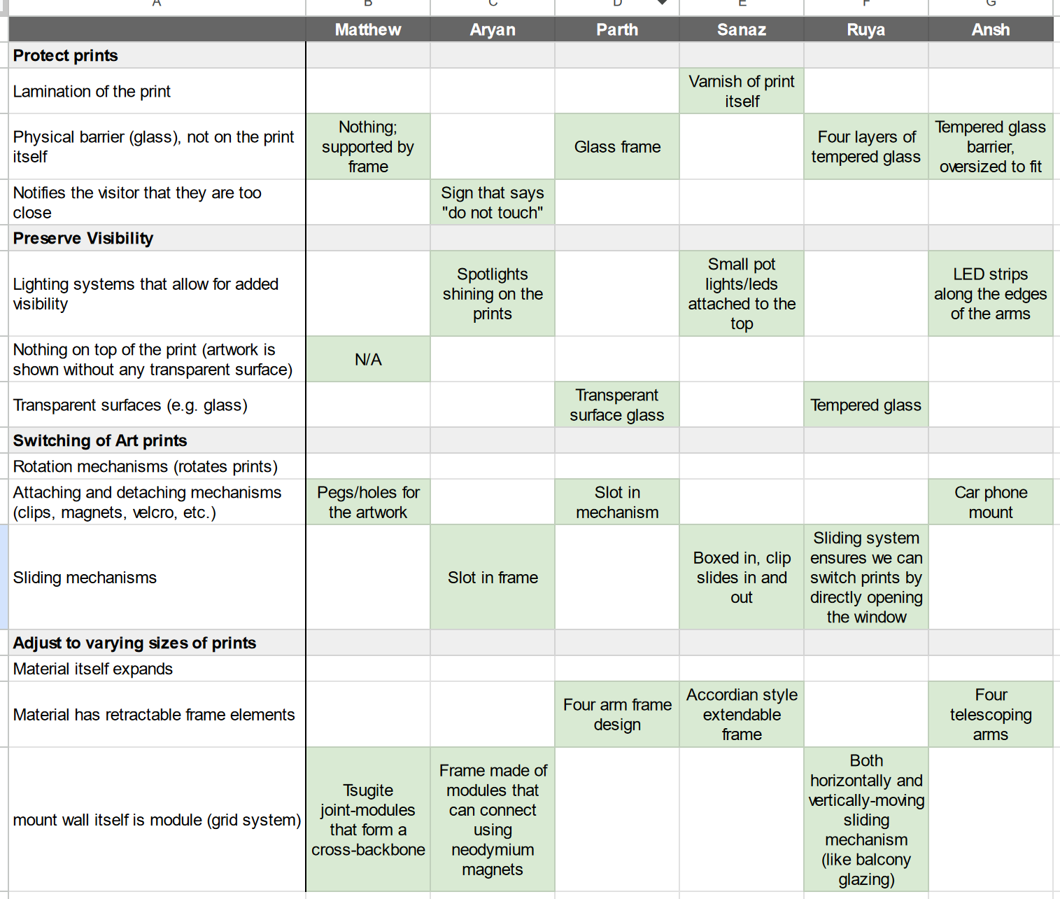
Figure 1. The categories we identified, the people they were assigned to, and the specific means chosen for each category, are shown.
The design of my solution
My solution was a system that, similar to my initial idea, utilized Tsugite joint modules to construct a larger frame to house the prints; they would use pegs to slot through the prints and into a module backbone.
Figure 2 depicts a rough sketch of my design, and is what I showed our client during our client meeting.
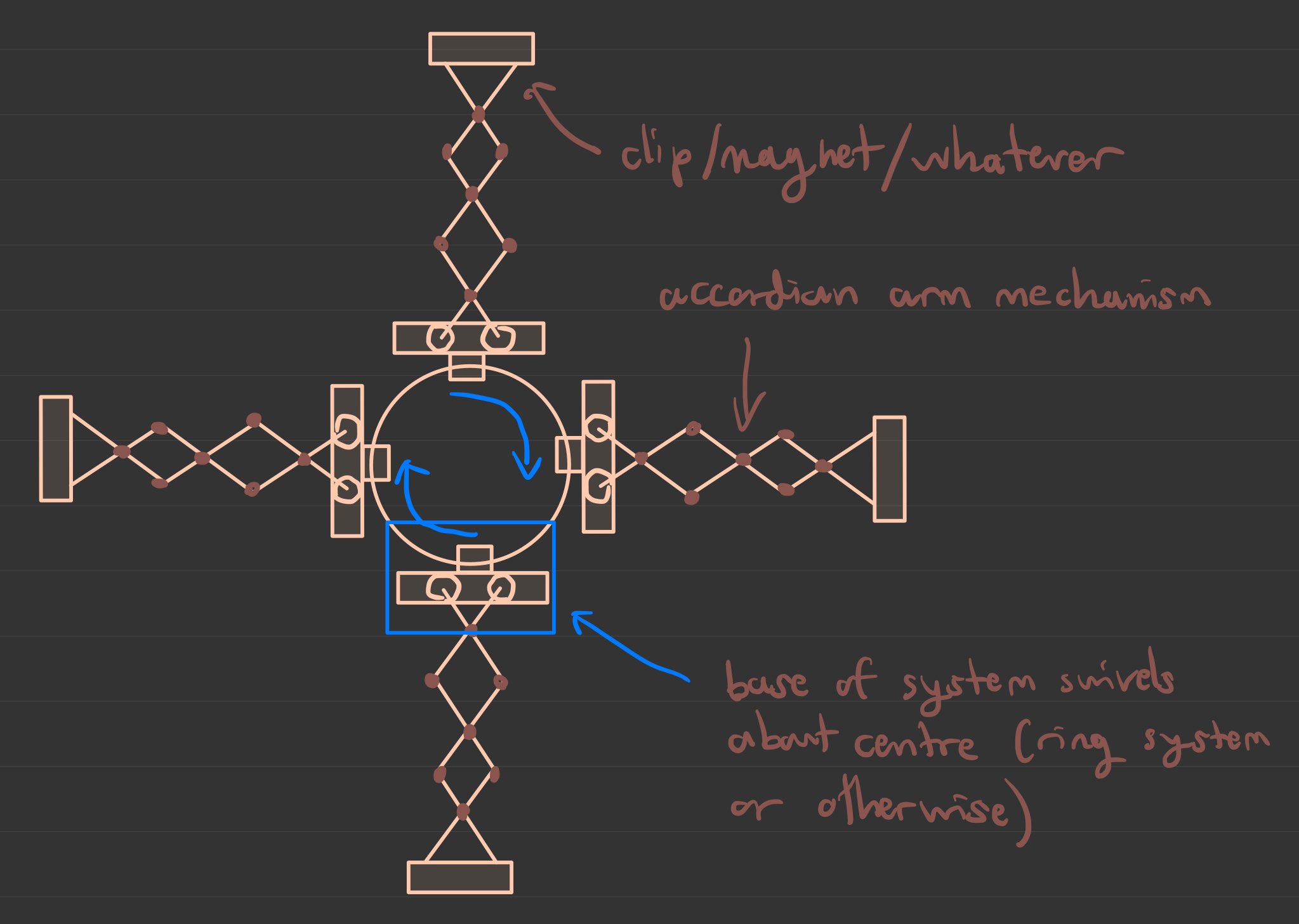
Figure 2. A sketch of the design I created, which involves Tsugite-joint modules.
Client Meeting #3 Notes
Friday, March 7th, 2025
(Note: I was not present for Client Meeting #2, as there were scheduling conflicts)
Before the meeting, we categorized our means (as part of solution generation) to make it easier to come up with full solutions. This is detailed in CDS Idea Generation Part 2.
Below are some notes I took during the meeting.
Size constraints
- Not much smaller than the chair to the top of the wall
- Some prints could extend across the entire wall
- Sasa suggested magnet system to attach the display units to the wall instead of drilling it each time.
Comments on designs
- "Wow, you guys are engineers or something?" - Sasa
- Attachment points solved by everyone, Sasa likes that
- Collapsing in both axes is "an important feature" according to Sasa
- Sasa likes the mechanical system of Ruya's design
- Sasa doesn't want to continue using the hooks.
- Sasa doesn't like the block system—might be too much work and blocks might get lost.
- For functionality or ease of use
- Sasa is worried about weight/sturdiness
- Must resist impact from bystanders
- Protective stuff in front of prints isn't that important for our purposes
- We don't need glass
- Glass typically is for artefacts that are airtight, which isn't needed
- Glass expandable window idea is difficult to keep airtight
- Again, for this project, since the prints are not valuable, this is not important for us.
- Two points of contact is okay
- Could also solve that by adding grooves to attachment point
- Framing or no framing?
- Spend more time on the expandable system, and sturdiness and weight of design, rather than the frame
- Adding rotation could be "cool" according to Sasa
- Sasa wants us to think about inorganic shaped-prints, e.g. a cloud
- Sasa wants us to think of a board of some kind that attaches to the prints without anything in front of the prints, which attaches to the display unit.
- "actually, just scrap that idea" - Sasa
- Brackets preferred over magnets because people steal magnets.
Other comments
- "They really make you work hard" - Sasa
- Lighting can be a separate thing, instead of something that we work on
CDS: ADD 2 Initial Idea
Tuesday, March 11th, 2025 (Edited March 20th, 2025)
The title of this section was changed to ADD 2, since we confirmed it to be our second alternative design
In the client meeting, our client mentioned that we should try to make our design account for inorganic print shapes (mainly non-rectangular), including the implementation of rotation. During tutorial (today), we were discussing how to implement this, and couldn't think of an idea that would effectively account for any shape of print.
During a leisurely stroll, I thought of an idea. Building on the accordion mechanism idea that one of our team members suggested to the client, which he liked, I drew a basic overview of a design that has four accordion arms that independently swivel about a central point, which is mounted to the wall via screws. This allows the mechanism to adjust to both different sizes and shapes of prints. Figure 1 shows a basic overview of the design, and Figure 2 shows the arms of the design swiveling and accommodating inorganic print shapes.
Figure 1. A basic drawing depicting an overview of the design I had come up with.
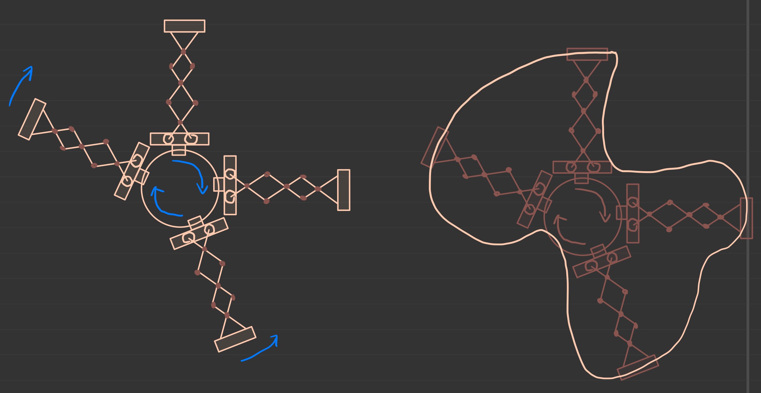
Figure 2. A basic drawing depicting the arms of my design swiveling independently about a central point (left), and the design accommodating an inorganic print shape.
Lecture 18 Questions (Reverse Engineering)
Thursday March 13th, 2025
In lecture, we were tasked with disassembling a mechanical pencil to reverse engineer it. Below are the answers to questions present in the slideshow.
What components are there?
As my team observed, there are 7 main parts of a mechanical pencil (the slides list ~12 parts, but due to time constraints, my team wasn't able to disassemble the pencil further). They are:
- Casing (including clip)
- Eraser
- Lead
- Tip (including grip, cone, and lead sleeve)
- Spring
- Dispenser
- Dispenser ring
- Shaft
The parts are drawn in Figure 1, and a photo of the parts is shown in Figure 2.
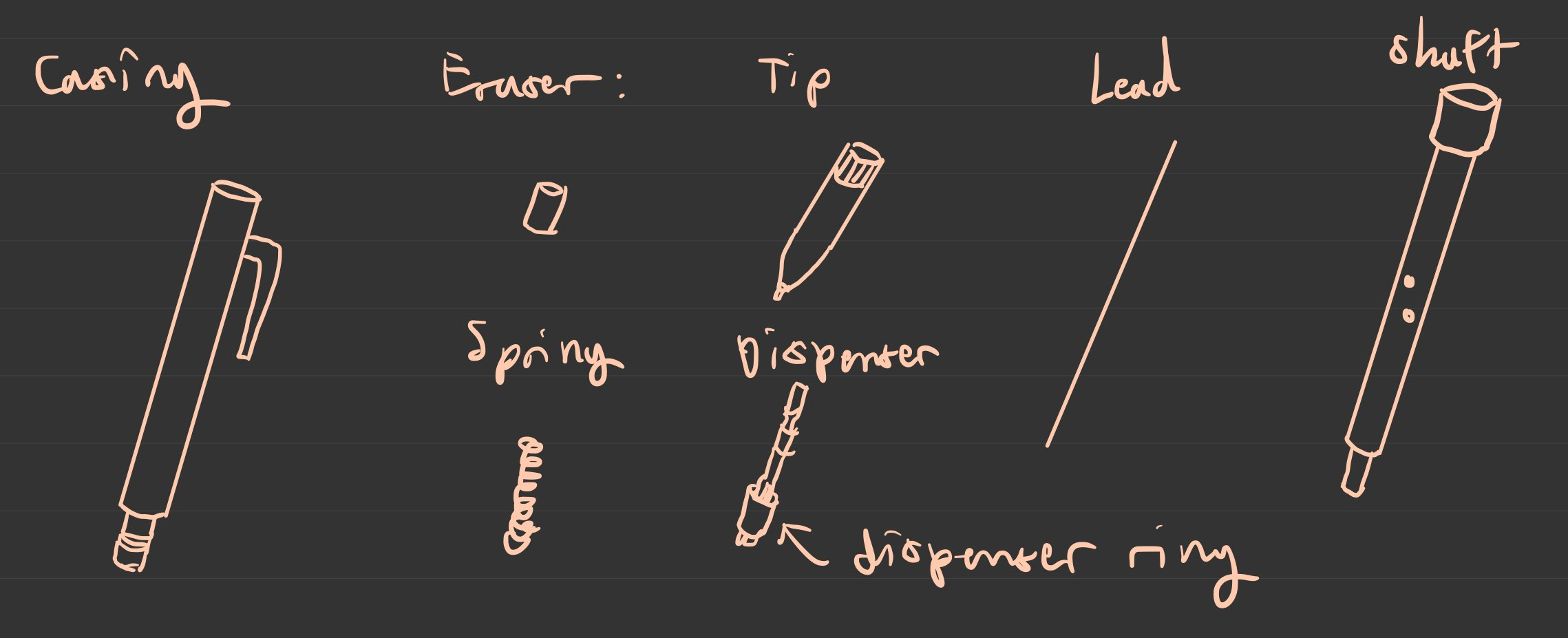
Figure 1. A drawing I created for each component of the mechanical pencil, as my team observed it.
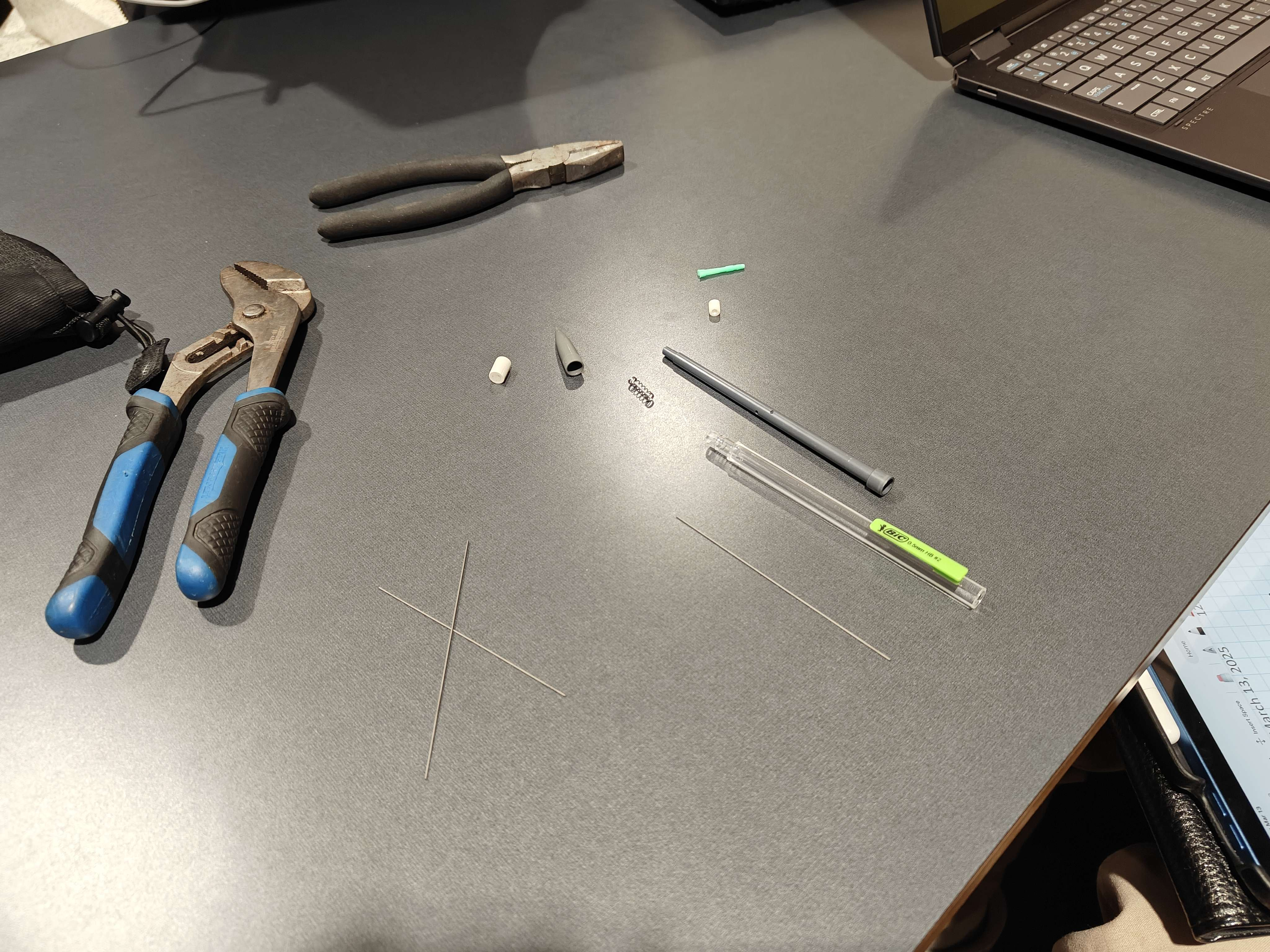
Figure 2. A photo of the mechanical pencil that my team disassembled.
Why are they there / what function does each component do
Table 1 lists all the components of the mechanical pencil and explains why they are there/what function they serve.
Table 1. Explanations for the functions and "why it's there" for each component we disassembled.
| Component | Reason for why it's there / what function it serves |
|---|---|
| Casing (including clip) | - To provide a comfortable surface that the user's hand can grip - (clip) to allow the pencil to be attached to clothing |
| Eraser | - To enable the user to correct mistakes easily - To act as a cap, preventing pencil lead from falling out, and allowing user to swap pencil lead once they've run out - To provide a surface that user can press to refill lead (pushes on shaft/spring mechanism) |
| Lead | - To allow the writing to occur (small portions of the lead are left on paper when friction/movement is applied) |
| Tip (including grip, cone, and lead sleeve) | - To provide a comfortable surface that the user's hand can grip - To guide the pencil lead (keeping it in the same position), thus allowing the user to make more precise movements |
| Spring | - To provide tactility/resistance to the refilling mechanism of the lead; user presses on top of eraser, which presses down on dispenser and its ring, and compresses the spring - To provide tactility/resistance so that the pencil can act as a fidget toy (possibly an unintended function) |
| Dispenser | - Funnels the pencil lead and pushes the lead downwards when the cap is pressed |
| Dispenser ring | - Part of the mechanism to push the pencil lead downwards, in conjunction with the dispenser |
| Shaft | - A guide along the middle of the pencil that aligns the pencil lead - Possibly provides extra structural rigidity to the pencil |
What objectives or constraints may have been considered?
Table 2 lists possible objectives and constraints that may have been considered in the creation of the mechanical pencil design.
Table 2. Possible objectives and constraints considered in the creation of the mechanical pencil design
| Possible Objectives | Possible Constraints |
|---|---|
| Should have diameter of less than 1cm(?), but greater than 3mm(?) | Must not have diameter greater than 2cm(?) |
| Should weigh less than 20g(?) | Must not have weight greater than 50g(?) |
| Should withstand x N grip force | Must withstand y N grip force |
| Should take less than z1 seconds to refill | Must take less than z2 seconds to refill |
After taking apart, can you put it back together?
It is very difficult to fully reassemble it because some of the plastic (particularly in the dispenser and dispenser ring) had to be deformed to be disassembled effectively.
Thus, it is likely that this pencil was not designed with reparability in mind.
CDS: ADD 2 Initial Prototype Drawings 1
Saturday, March 15th, 2025
The title of this section was changed to ADD 2, since we confirmed it to be our second alternative design
Carrying on with the idea from my initial idea stage, I decided to create some more formal drawings to represent the second alternative design, as well as further detail how the design works, so that I could better communicate with my team members.
Overview
The design houses four accordion-style arms, which extend or retract. Two arms are sandwiched in the same plane by two circular centerpieces, and the pins of each bar of the arms slide along these circular centerpieces to allow rotation and arm extension/retraction. Below this sandwich is another duplicate sandwich, rotated 90 degrees. As a whole, there are four arms, which extend/retract to accommodate different print dimensions and shapes. A single plane (two arms only) is shown in Figure 1.
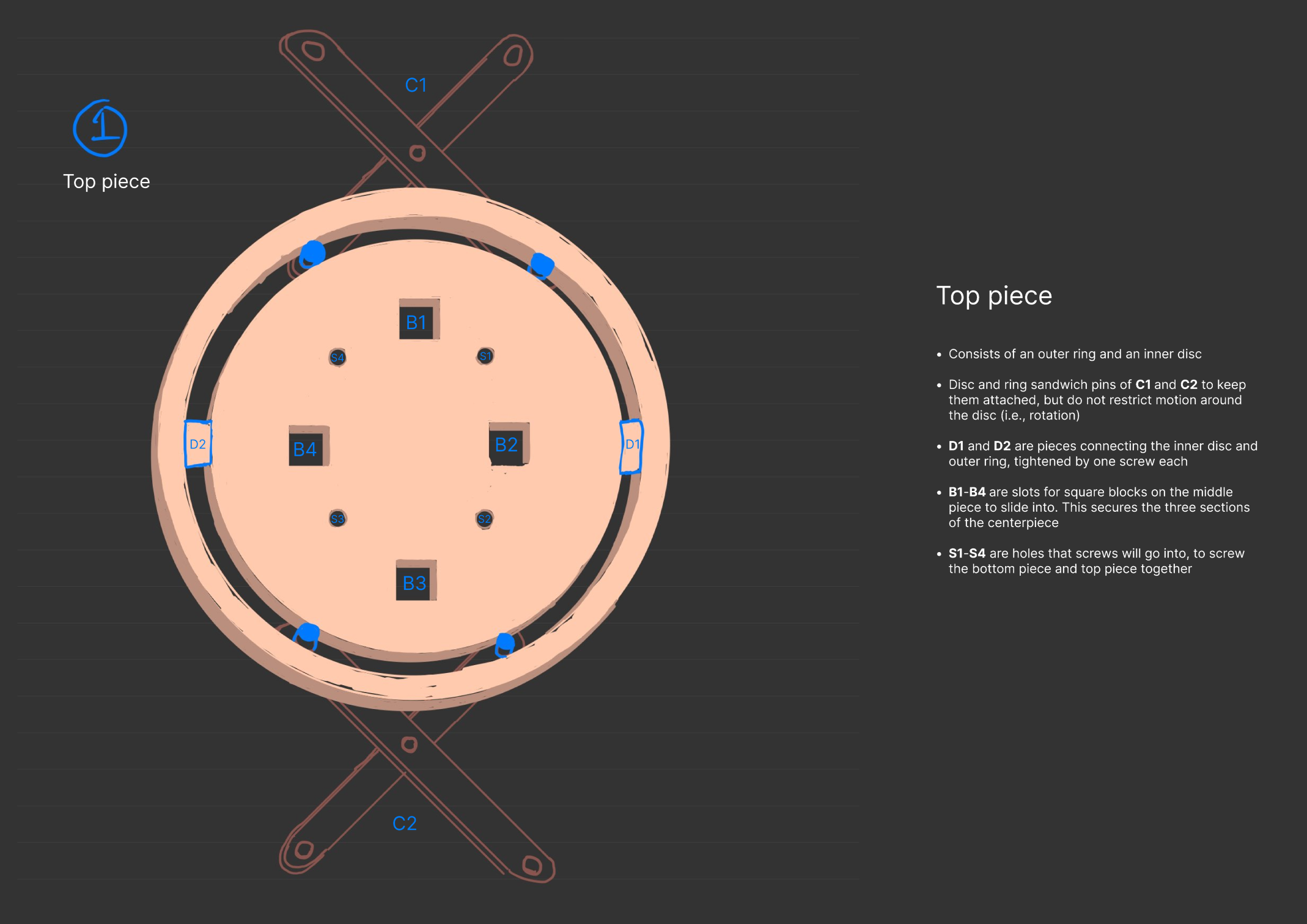
Figure 1. Extended (left) and retracted (right) views of the design in one plane.
Accordion bars
Each arm will be composed of smaller bars, which pivot about interconnected joints to allow the arm to extend or retract (see Figure 1). I designed these arms to be connected by M6 machine screws and M6 machine screw nuts, and so there had to be two bar designs: a top and a bottom. These are depicted in Figure 2 and Figure 3 respectively.
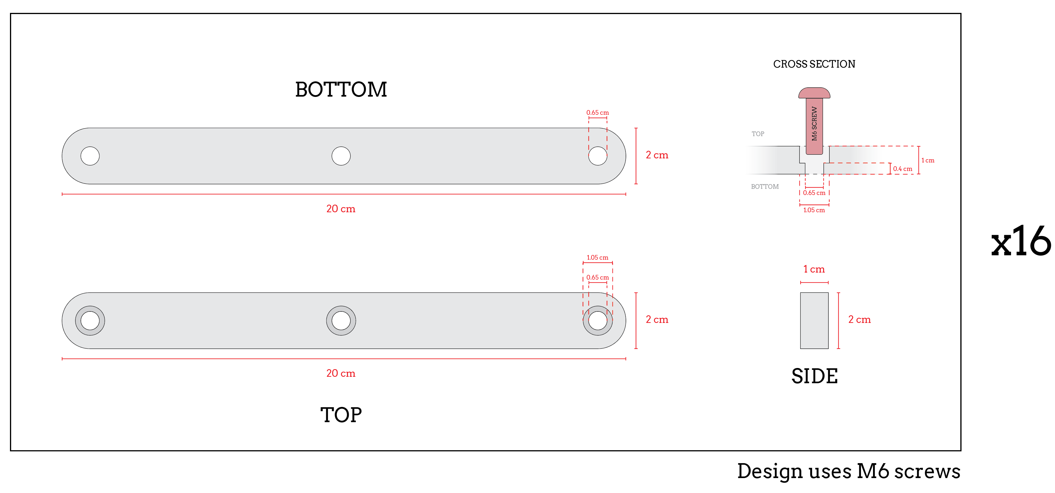
Figure 2. Top bar piece dimensions.
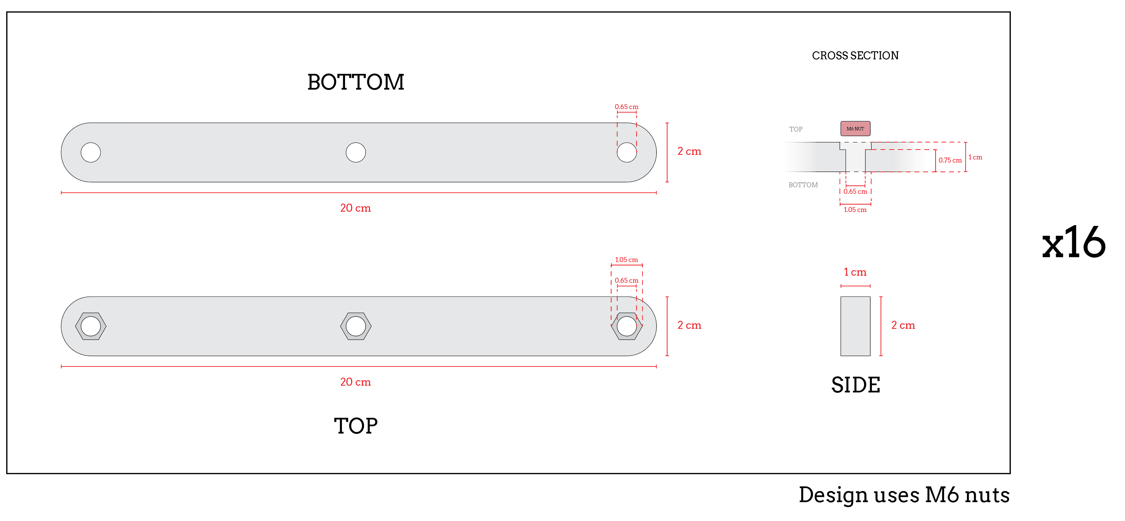
Figure 3. Bottom bar piece dimensions.
Clamp
To hold the prints in place, the ends of each arm had to be outfitted with some sort of mechanism to grab the prints. In my design, I opted for a quick-release swiveling clamp system, which uses neodymium magnets to hold the print in place. To release the print, the user would only need to pull on the clamp and swivel it around the cylindrical bar that it is attached to. I drew a basic rendition of this mechanism in Figure 4.
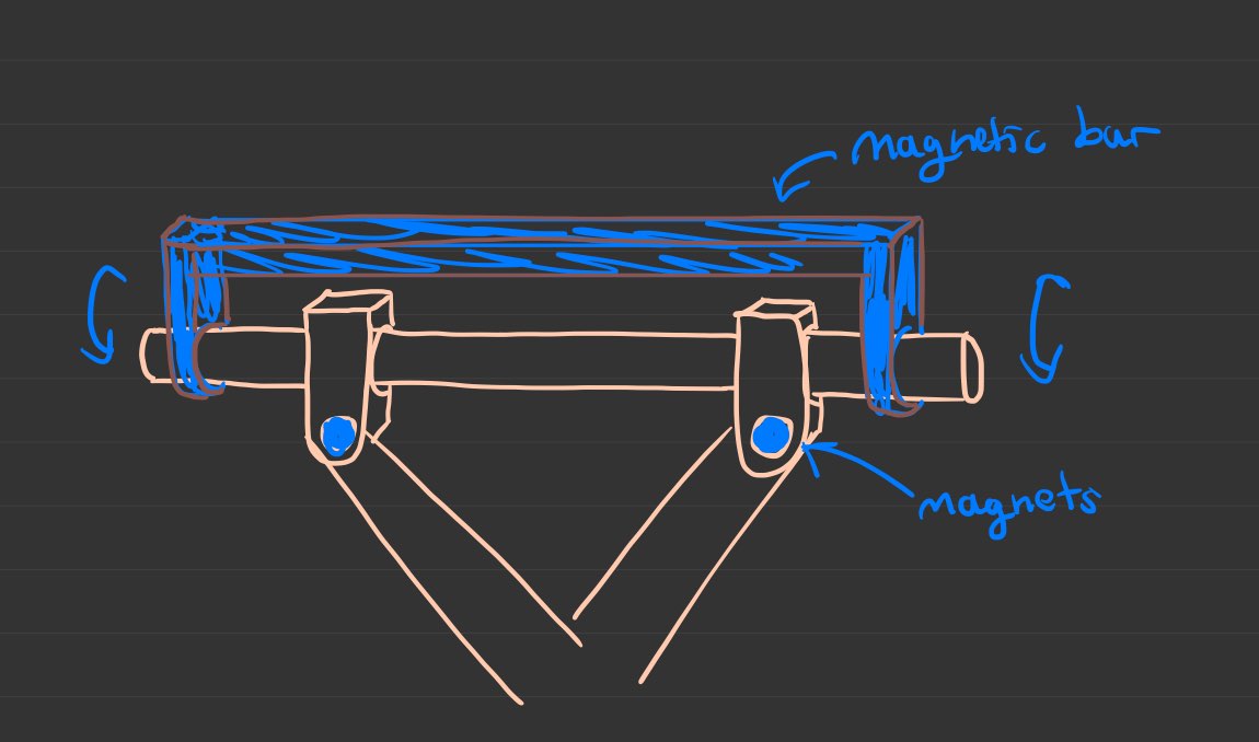
Figure 4. The swiveling clamp system I designed is depicted.
CDS: ADD 2 Initial Prototype Drawings 2
Tuesday, March 18th, 2025
I decided to create a more detailed drawing of the centerpiece, expanding on the drawings in CDS ADD 2 Initial Prototype Drawings 2. This was to add clarity to my design, as my teammates were confused as to how the design would work. The top, middle, and bottom pieces are detailed in Figure 1, Figure 2, and Figure 3 respectively, and a cross-section of the pin system is depicted in Figure 4.
Figure 1. The top piece of the centerpiece of ADD 2.
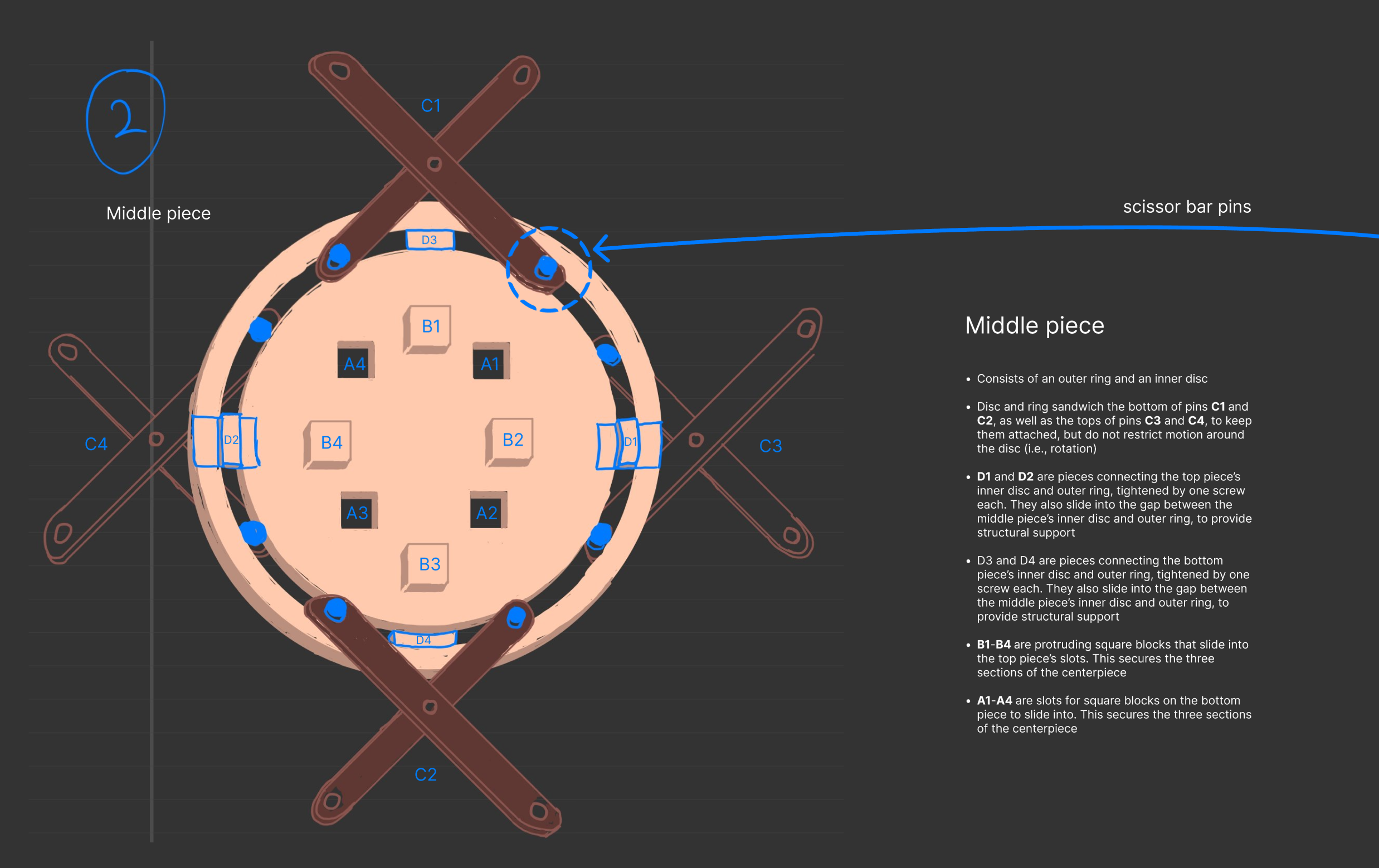
Figure 2. The middle piece of the centerpiece of ADD 2.
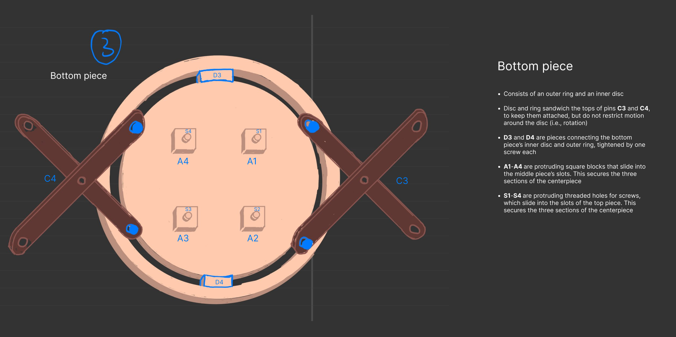
Figure 3. The bottom piece of the centerpiece of ADD 2.
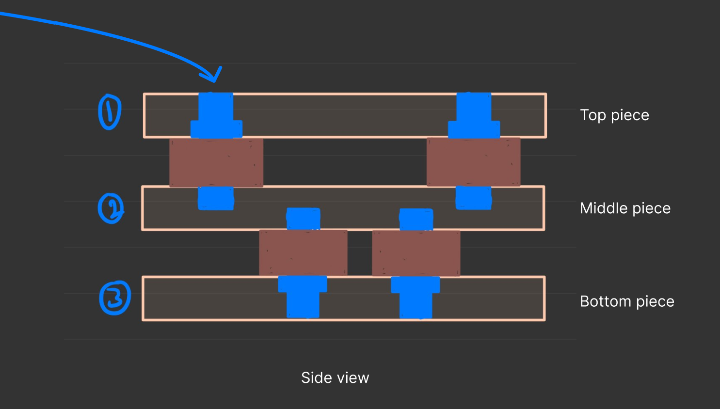
Figure 4. A cross-section of the centerpiece, depicting the pin-system mechanism.
CDS Debrief
Wednesday, april 2nd, 2025
In a Microsoft Teams meeting, our TA gave us a debrief on her feedback for the CDS. Below are some jot notes I took.
- Pay attention to the capitalization of design names
- The period should come after the reference!!
- Diagrams
- Do not use hand drawn diagrams, it is unprofessional
- PCD
- Put the reference to appendix further up
- Add more information on the weighted decision matrix results as a whole
- MOS
- Add way more detail on the where, when, what, etc. in each stage of the process of the MOS
- Locations
- What kinds of materials
- Where did you source them
- Where did you build it, and how
- Where and how are you getting prints?
- What tests did we do, how did we do them, and why are they reliable?
- Next steps?
- Add way more detail on the where, when, what, etc. in each stage of the process of the MOS